
Breakdown and Evaluation
I've been thinking I am going to do this blog but haven't had just the "right" plane to document the process… until now. I know there are an abundance of these tutorials all over the internet so I don't pretend to be breaking any new ground here. I just know we all find our own little tricks and tips so I thought I'd show y'all how I do it and hopefully, there's a useful tidbit in here for someone.
Here are some good articles from wkfinetools on repair and rehabbing planes
And, here is DonW's restoration tutorial on his site. Be sure to poke around both of these sites. There is a plethora of useful information on both!
Also, search Lumberjocks. There are good tutorials in the blog section here too. Like I said, I just wanted to add a little more to the pot for folks to sample.
I chose to document this one because this plane needs the full treatment. Let me say up front, not all planes need ALL of the things done that I will do to this one. But this one came to me with nearly every bit of the surfaces laden with rust so it will get the "deluxe" package")
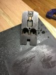
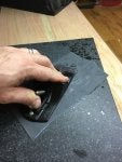
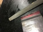
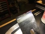
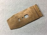
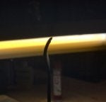
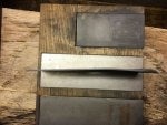
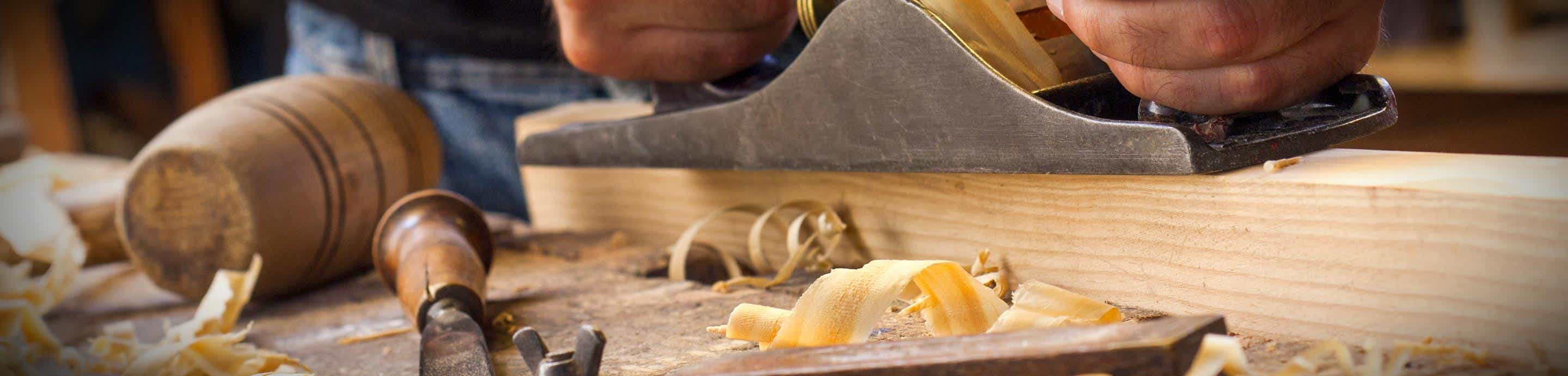
Anyway… on with it! Here is the patient:
![Image]()
![Image]()
A Miller's Falls 22CB (equivalent to Stanley #7) jointer. I have grown quite fond of MF planes lately so I have been watching for good buys. I didn't really need another jointer but I got this one at a very good price so I snagged it.
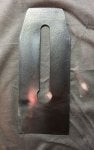
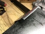
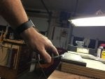
The first thing I do is break down the plane and check to see if all the parts are proper and in good repair. In this case, the plane has all of it's original parts and everything seems to be in pretty good condition with the exception of the rust. I'm betting this was a hard-used plane but that the owner retired or passed-on and it has been sitting in a barn neglected since then. Why? Well, aside from rust, the plane is in very good shape. And, the iron is very short. Actually one of the shortest I've seen on a jointer plane, and it's the original. That tells me it's been sharpened many times over the years.
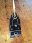
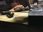
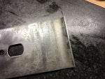
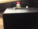
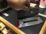
Here is this guy broke down:
![Image]()
So, what needs to be done?
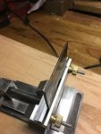
Well, before I do anything, I really check the base out. No cracks or breaks, sole is decently flat when checked with a straight edge and all the right spots are machined and threads are all in good shape. Japanning is a different story.
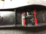
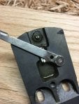
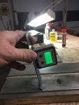
Next I check the frog over well. All looks good. Lateral lever and depth adjuster function well and machining is proper to mate the frog to the base. We'll fine tune that later on but for now, I just want to make sure it's worth investing the time.
It is.
So, step 1 is to do a good evaluation of the plane you're working on, make sure it's worth the effort to restore it, decide what level you want to rehab it to and make a list of what all that entails.
Like I said, I'm going full-bore on this one. So what will that include?
So we'll start next time with getting rid of all this rust and preventing it from coming back.
Thanks for reading!
I've been thinking I am going to do this blog but haven't had just the "right" plane to document the process… until now. I know there are an abundance of these tutorials all over the internet so I don't pretend to be breaking any new ground here. I just know we all find our own little tricks and tips so I thought I'd show y'all how I do it and hopefully, there's a useful tidbit in here for someone.
Here are some good articles from wkfinetools on repair and rehabbing planes
And, here is DonW's restoration tutorial on his site. Be sure to poke around both of these sites. There is a plethora of useful information on both!
Also, search Lumberjocks. There are good tutorials in the blog section here too. Like I said, I just wanted to add a little more to the pot for folks to sample.
I chose to document this one because this plane needs the full treatment. Let me say up front, not all planes need ALL of the things done that I will do to this one. But this one came to me with nearly every bit of the surfaces laden with rust so it will get the "deluxe" package
Anyway… on with it! Here is the patient:
A Miller's Falls 22CB (equivalent to Stanley #7) jointer. I have grown quite fond of MF planes lately so I have been watching for good buys. I didn't really need another jointer but I got this one at a very good price so I snagged it.
The first thing I do is break down the plane and check to see if all the parts are proper and in good repair. In this case, the plane has all of it's original parts and everything seems to be in pretty good condition with the exception of the rust. I'm betting this was a hard-used plane but that the owner retired or passed-on and it has been sitting in a barn neglected since then. Why? Well, aside from rust, the plane is in very good shape. And, the iron is very short. Actually one of the shortest I've seen on a jointer plane, and it's the original. That tells me it's been sharpened many times over the years.
Here is this guy broke down:
So, what needs to be done?
Well, before I do anything, I really check the base out. No cracks or breaks, sole is decently flat when checked with a straight edge and all the right spots are machined and threads are all in good shape. Japanning is a different story.
Next I check the frog over well. All looks good. Lateral lever and depth adjuster function well and machining is proper to mate the frog to the base. We'll fine tune that later on but for now, I just want to make sure it's worth investing the time.
It is.
So, step 1 is to do a good evaluation of the plane you're working on, make sure it's worth the effort to restore it, decide what level you want to rehab it to and make a list of what all that entails.
Like I said, I'm going full-bore on this one. So what will that include?
- Japanning is only ~50% and a lot of that is crumbling. So, I'll be re-finishing the base.
- Frog is in good shape except for some rust. Needs de-rusting but paint is good (although it's not that sexy Millers Falls red so it may be getting a paint job anyway - we'll see)
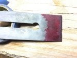
- Iron may be salvagable but it's already pretty short and there's sever pitting that will have to be ground back. We'll give it a shot but we may have to replace it.
- Hardware's all solid but has surface rust. We'll remove the rust and polish it up.
- Tote and knob are rock solid - no cracks or previous repairs - but, the finish is hideous! Can't tell if that's paint or some kind of film-finish-gone-wrong. Either way, they will be kept but will be taken down to bare wood and refinished.
- Lever cap needs rust removed and polished up. May paint the recess red if I decide to paint the frog red. For the record though, this plane came from the factory with the black frog and no paint on the lever cap.
- Cap iron needs rust removal and polishing. Will need to grind out pitting at front and see if it can still be properly mated to the iron. May have to replace?
So we'll start next time with getting rid of all this rust and preventing it from coming back.
Thanks for reading!